This project was conducted by me during winter 2013 student exchange in Akita National College of Technology, Japan. For the research, I was given two pneumatic actuators for mimicking the motion of the caterpillar. Similar type of gait, named Rectilinear locomotion, is found in nature.


Despite slow speed, such way of wheel-less propulsion allows for large vertical load.
Remote control
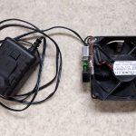
Remote control consists of 2-axis potentiometer joystick, Atmega328p microcontroller and nRF24l01 2.4 GHz radio module. Because it is powered by pair of alkaline batteries, Atmega’s brownout detector (BOD) is set to 1.8 V to inhibit probable low-voltage operations.


Joystick data is sampled with ADC 430 times a second and processed with the CORDIC algorithm (which converts from Cartesian to Polar form faster than normal math library). Depending on the velocity setting, information is modified and then fed to the RF transmitter through SPI. Periods of while-loop execution in active and standby mode are equal to 2.315 ms and 14.50 ms respectively. Speed of the actuator locomotion can be finely controlled with slight tilt of the joystick. To make motion speed control even more flexible, there are three limits on the top actuator frequency: 0.5 Hz, 0.7 Hz and 0.9 Hz. Those are indicated by LED’s and can be selected by pressing the joystick shaft.


Remote control board was manufactured by chemical etching from photosensitive Phenolc paper (FR1-1t) sheet.
Robot chassis
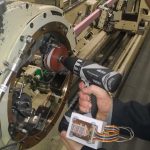
Control circuit of the chassis consists of filtered switching power supply (based on LM2594), Atmega328p microcontroller, nRF24l01 2.4 GHz radio module and a 4 LED gauge (remaining gas indicator). Actuators are pressurized by two solenoid pneumatic valve arrays (CKD Automation). Valves are controlled individually by microcontroller via sink drivers. Zener diodes are used to suppress current surge from solenoids.


During program operation, timer module is continuously updated with pattern period value, which is calculated from the received data. Timing of the actuators is performed in two separate compare registers, providing independent intervals for each sink driver. Forward, backward and rotary motions are performed by switching the actuator motion direction while varying speed symmetrically, according to the joystick bar incline. In comparison to the 2.315 ms while-loop execution period of the remote control, robot driver program rotates in 535 μs.


During robot movement, exhausted air is counted, and remaining gas value is displayed at the indicator. From time to time, air gauge information is saved to the internal EEPROM memory. When system boots up again, this information is recalled and updated.


Robot PCB was manufactured by chemical etching from photosensitive glass-reinforced epoxy laminate (FR4-1.6t) sheet.
Perfomance
Robot travelling tests were conducted on the flat surface covered by paper. Friction coefficient was kept exactly the same as in the original test. With slight increase in operating pressure of the actuator, propulsion profile is improved:


Following characteristics have been observed (given values are approximate):
| Direct sight remote range | 75 m |
| Range through the wall | 15 m |
| Top speed | 6.5 mm/s |
| Standby lifetime | 48 h |
| Active lifetime (batteries) | 40 m |
| N2 tank active lifetime | 3 m |
| Robot dimensions (W L H) | 300 x 197 x 75 mm |
| Robot weight | 1137 g |
The overall cost of the control circuitry components (excluding manufacture, actuators, solenoids and gas bottles) is about 12000 yen, which is approximately 90 euro.