International Sensor Development Project was a cooperation work between Metropolia UAS and University of Osnabrück which included eight participants from each institution. The purpose of the project is to build domestic weather station prototype, collecting as many useful data as possible. Team of four students from electronics department were to create the Indoor Sensor Unit (ISU). Four students from embedded programming were working on Central Processing Unit (CPU), and eight students from Germany were building Outdoor Sensor Unit (OSU).


According to the plan, outdoor and indoor units would be connected with RF link. Main processing block would be wired with other microcontroller (ISU), which is gathering data from indoor sensors. Our team has implemented a system based on three sensors, collecting all readings together and sending them to the CPU. In the project I took care of organisation, programming, and some of electrical design.
Pressure sensor and communication
Bosch Sensortec BMP085 was selected because of its high sensitivity and digital I2C interface. The MSP430 microcontroller has internal hardware logic for the I2C communications. This circuits can operate independently of processor, and whole process of communication is based on writing data to the registers. In order to avoid polling, ISU communication system was designed using interrupts, so weather station’s CPU could request values at any time. To realize that, Interrupt Service Routine (ISR) has been written as complex switch-case state machine; global state variables have been changed in the main program loop.
#pragma vector = USCIAB0TX_VECTOR
__interrupt void USCIAB0TX_ISR(void)
{
if (IFG2 & UCA0TXIFG) { //spi mode
UCA0TXBUF = spidata[spictr++]; //feed the CPU
if (spictr > 10) {spictr = 0;}
spifg = 1;
}
if ((IFG2 & UCB0RXIFG)|(IFG2 & UCB0TXIFG)) { //i2c mode
switch (state){
case 0: { // init state tx addr
if (~UCB0CTL1 & UCTXSTT) { //xND STEP buffer steady while slave ack + transmission 1st
UCB0CTL1 &= ~UCTR; //then restart in rx mode straight after
UCB0CTL1 |= UCTXSTT;
IFG2 &= ~UCB0TXIFG; //clear interrupt flag
state = 1; //init -> aquisition state
}
else {UCB0TXBUF = i2ctx;} //1ST STEP line isnt busy buffer steady while slave address going
break;
}

//here will go after init mode first byte of calibration data being received

case 1: { //acquisition state
if (rxbyte) { //msb catch
i2crx = UCB0RXBUF << 8; // Get received byte
rxbyte--; // next -> lsb
UCB0CTL1 |= UCTXSTP;
}
else {
i2crx |= UCB0RXBUF; // Get final received byte, Combine MSB and LSB
__bic_SR_register_on_exit(CPUOFF + GIE);
}
break;
}

case 2: { //writing control byte
if (~UCB0CTL1 & UCTXSTT) { //xND STEP buffer steady while slave ack + transmission 1st
if (txbyte) {
UCB0CTL1 |= UCTXSTP; //stop
IFG2 &= ~UCB0TXIFG; //clear interrupt flag
txbyte--; //reset txbyte
}
else {
UCB0TXBUF = ctrlbyte; //pressure control byte mode 1
txbyte++;
}
}
else {UCB0TXBUF = i2ctx;} //1ST STEP line isnt busy buffer steady while slave address going
break;
}
}
}
}
As hardware-timed code is based on interrupts, microprocessor can perform other tasks during communication. Instead of that, to keep the operation simple, processor is sent to low-power mode until ISR “wakes” it up when transmission is done. Other situation when processor is interrupted – the CPU request via SPI module. One of interrupt-driven design drawbacks is a difficult debugging process.
At the beginning of the ISU module operation, 11 calibration coefficients are downloaded from the sensor EEPROM for later use in data conversion process. Microconroller begins BMP085 internal ADC conversion by writing bytes into its control registers, and then goes into low-power mode. When conversion is finished, sensor emits an interrupt signal, which restores the controller operation. Raw data is then downloaded and processed with calibration data, resulting in precise pressure reading.
Temperature/humidity sensor
Black sheep of the project was the Maxdetect RHT03 sensor. Despite low cost, the reading protocol was troublesome. Only one wire is available for transmission, and both devices could pull it low. Data is requested with special sequence of high and low signals. What followed is the train of pulses, and bits were encoded by pulse width.


I managed to get the data out of the sensor using while loop polling of the pin, followed by decoding “ones” and “zeroes” from the loop iteration values. The format is following : [2 byte humidity] [2 byte temperature] [1 byte checksum].
CO2 sensor and ADC
FIGARO TGS 4161 carbon dioxide sensor is an analog device, which has special heating resistor integrated in the package. When this resistor is powered, solid electrolyte pad is generating electromotive force on the sensor electrodes. This EMF is constantly changing with time, and the rate of change is proportional to the carbon dioxide concentration. Total ΔEMF measured during 1.5 minutes of heating is converted to the CO2 concentration with logarithmic table.
ISU program, operating as state machine, is alternating between pressure and humidity measurements every five seconds. Each 90 seconds program toggles heater of the CO2 sensor and making ADC samples.


The delay time is counted with timer peripherals, as they remain operational during low power mode and recover the processor from sleep. Logarithmic dependence and reduced ADC resolution due to delta calculations imposed sensitivity problems. In order to avoid complex calculations, discretized logarithmic look-up table of ninety integer values is used to find CO2 concentration.
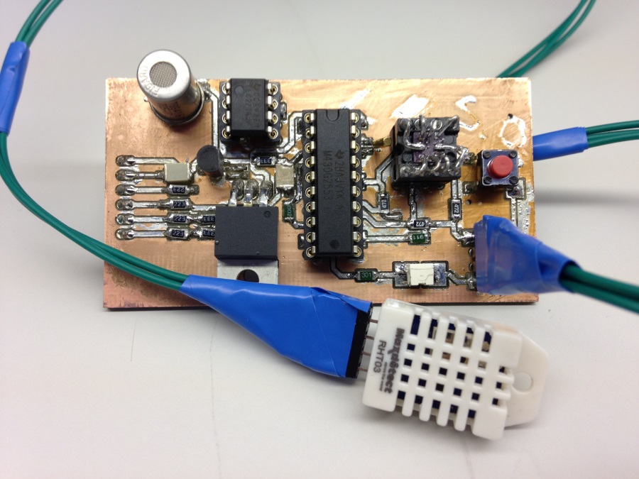
Electrical design
Indoor Sensor Unit is made such that it is plugged onto CPU with SIP connector as a module. ISU circuit is using two voltage levels, original 5V TTL voltage line is taken from CPU and fed into CO2 sensor heater with a transistor switch. Other elements are powered by a linear 3.3V regulator.


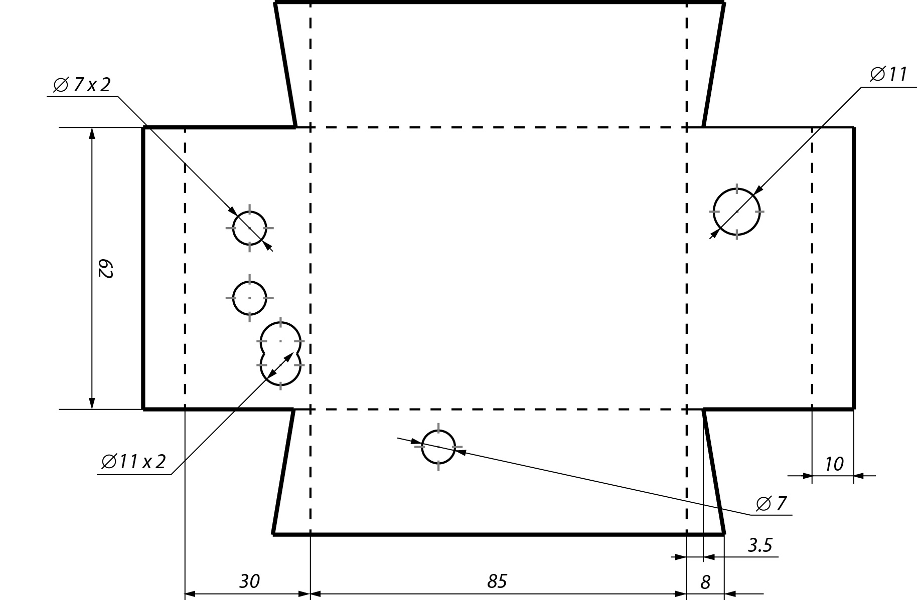
SPI lines are stepped down from five volts with a cheap solution – voltage divider. CO2 sensor electrodes are buffered with an unity gain op-amp. LED is meant to indicate every sensor reading made by the system. Push button is connected to the reset pin of MSP430. One 32kHz crystal is added as the timer clock to count long and precise delays between ADC readings. Double layer printed circuit board was manufactured with milling machine.
System characteristics
| Range | Precision | Accuracy | |
| Temperature | 0-60°C | 0.1°C | ±0.5°C |
| Relative humidity | 0-95% | 0.1% | ±2% |
| Atmosperic pressure | 300-700 hPa | 10 Pa | ±100 Pa |
| Carbon Dioxide | 350-3500 ppm | variable | ±20% |
Temperature, humidity and pressure values are updated every 10 seconds. CO2 reading is made each 3 minutes. The data is requested from the ISU according to the standard SPI protocol, by just putting the Slave Select line low. Following sequence of 11 bytes will be sent back :
[ 0xC0 0xFF 0xEE (sync bits) ] [2b temperature] [2b humidity] [2b pressure] [2b CO2]