The device is a portable drill, modified in such way, that torque, applied to the shaft is detected and value is shown to the user. Given that the pull of DC motor is directly proportional to the current drawn from the battery, the main purpose of modification is current sensing with shunt resistor.
Starting from the beginning, our team has been trying to test the drill motor with some kind of improvised hand-made brake. Even though we had placed shunt resistor and made amplifier and microcontroller ready , this approach did not work. Situation has changed later, when we got access to electromagnetic torque machine, allowing to simulate precise braking. Collected readings have been very noisy, but linear. Next bottleneck was to find right components and apply proper filtering. After a while, I was given an AD8120 current sensor by classmate. With some prototyping, all components were confirmed working and I proceeded to design first sensing board.
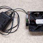
Main challenge was to prevent massive electromagnetic noise, generated by the drill motor. From a big tin can I made a small box, which is wide enough to fit MSP430 Launchpad development board with sensing board mounted on top of it.


The box prevents all the sensing circuit parts from EM interference. Cores of two coaxial cables carry voltage from the 0.01Ω hot wire shunt resistor placed in the handle of the drill. Cables are screwed onto the SMA connectors, putting the battery ground to the box. Based on the current sensor IC and box limitations, I have designed a sensing circuit. Three voltage signals from the inside of the drill – Vcc, ground and shunt allow for measuring not only the shunt voltage drop, but the battery voltage as well. For this, two ADC channels of the MSP430 are used consecutively.


Shunt voltage signal is fed to low pass filter, then pre-amplified by AD8120 and put to the second amplification stage with variable gain. Drill battery signal is converted with low-dropout regulator to power all the sensing circuitry. Same line (battery Vcc) is also scaled down with a voltage divider, filtered and buffered for ADC.
Microcontroller is programmed to sample and average both ADC channels, each second displaying momentary readings to PC via serial port. User can interact with program, selecting some of sample points by pressing keys. MSP430 is saving these points to flash, and then prints them in CSV format when they are needed. First readings look quite promising and clean:

Using this data, a simple program implementing first order linear model has been written by me and my colleague. To show the results, 7-segment LED displays have been used, backed up with multiplexing sequence from the microcontroller. Dedicated circuit boards for microcontroller and display were designed by my colleague, resulting in alltogether standalone measurement system.


The box has been modified to be easily detachable from the drill. Measurement device is powered from the drill battery, and controlled from the display board. It is possible to reset the microcontroller or calibrate reference of torque calculation.

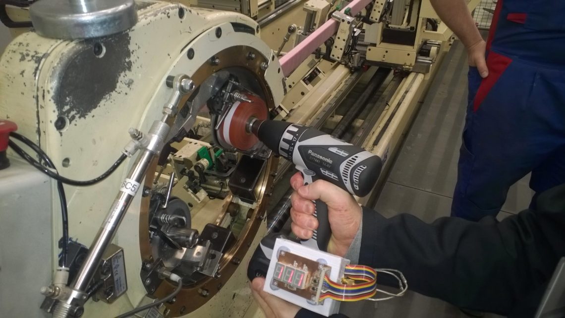
The EM emission scan test results of the device are satisfactory. System was tested on its main target application – real taping equipment in ABB factory in Pitajänmäki, Helsinki. The results were close to the values measured by manual method, however there are still many improvements can be made to match device for actual application.
Specifications of the torque meter are following:
| Measurement range, high gear | 0 – 3.2 Nm |
| Standard deviation | 0.05 Nm |
| Rotation speed, high gear | 1400 rpm |
| Rotation speed, low gear | 400 rpm |
| Battery life time on half load | ~ 7 min |
| Device standby life time | over 3 hours |